CSP (Concentrated Solar Power) solar fields are basically a set of mirrors (also called "heliostats") that always move to reflect the solar radiation towards the receiver. The number and surface of the mirrors can be very different from field to field, but in principle the energy reflected by a total mirrored surface ranging from a few hundred to a few thousand m2 is concentrated on a single receiver. Fig. 1 shows the basic scheme of a CSP field: in dark red, in the foreground, the heliostats, and in green (on the Z axis) the receiving surface. Thus a “spot” is produced on the receiver in which the radiation reflected by the mirrors is concentrated.

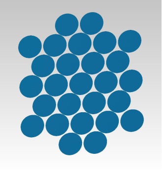
An efficient collection of solar energy is obviously one of the keys to the success of a CSP system. This does not only depend on the number and surface of the heliostats, but above all on the correct optical design of the system. In almost all systems the heliostats are the only mirrors present, rarely is another mirror or mirror system (called “secondary”) present. Heliostats can be basically of three types: flat, curved or compound (faceted). The first solution is constructively simpler, but the size of the spot is generally larger than that which would be obtained using the other two types of mirrors (especially for large systems, however, this difference can be negligible); another disadvantage is the need to use a greater number of movements for the same total surface area of the mirrors. The second method is convenient, especially for small plants, but checking the correct curvature of the mirrors during the production phase can be complex (and therefore onerous). The third system is used above all for large systems, with single large mirrors, even up to tens of m2; generally requires a low number of movements but the assembly of the composite mirror (which is formed by a matrix of smaller mirrors) is generally complicated. In Fig. 2 there is an example of a composite mirror (each mirror, in this case, has a spherical curvature; the circular shape is adopted for reasons of constructive simplicity, even if it obviously involves some flow losses).

Once the type of heliostats to be used has been chosen, it is necessary to define the position of the individual heliostats, i.e. the distance at which the adjacent heliostats must be placed and the distance between the rows of heliostats. It is not possible to evaluate these distances only on the basis of the mechanical encumbrance, since there are the phenomena of "shadowing" (the shadow that a heliostat produces on an adjacent heliostat, which will therefore collect less energy) and "blocking", that is to say the interception of rays reflected by a heliostat and directed towards the receiver by the heliostat in front of him. Shadowing and blocking strongly depend on the position of the sun, and therefore vary according to the time of day and the season: also in this case it is necessary to seek a compromise between performance (directly proportional to the density of heliostats with respect to the surface of land used) and constancy of performance (higher in the absence of shadowing or blocking, that is, with a lower density of heliostats).
The size of the spot on the receiver depends, in addition to the characteristics of the heliostats, both on the solar divergence (i.e. the fact that the solar radiation does not come exactly from a single direction) and on the inevitable construction tolerances of the system (for example , from the actual flatness of the mirrors); both cause a broadening of the beam directed towards the receiver, and on this the spot produced by the solar rays reflected by the mirrors will be neither a point nor a defined circle or rectangle, but an oval or circular figure that fades outwards (i.e. a species of Gaussian). In Fig. 3 you can see the simulation of a spot produced on the receiver.

The fact that the spot does not have well-defined edges entails the need to choose the size of the receiver that represents the best compromise between radiation collection and losses by convection or radiation. It is obvious that this goal can only be achieved by taking into account the size (or rather, the shape) of the spot and therefore the type of heliostats. In fact, the greatest difficulty relating to the design of the field lies in the interconnection that exists between all the parameters and variables of the CSP system, so it is impossible to design the field without taking into account the receiver and vice versa.
The receiver can consist of a surface, a set of tubes or a cavity; in the latter case a hole of suitable dimensions is made in it which allows the entry of the beams coming from the mirrors and which, in fact, represents the receiving surface. In any case, the purpose of the optical design of the receiver and of the choice of materials is to maximize its absorption, and in some cases to ensure a certain uniformity of irradiation on the receiver.
CNR-INO Istituto Nazionale di Ottica - Largo Fermi 6, 50125 Firenze - Tel. +39 05523081 - P.iva 02118311006 - Info: info@ino.cnr.it